Cfl Ups Circuit Diagram
Ups schematic circuit diagram Cfl inverter watt pull Circuit ups supply power diagram seekic basic
Draw your wiring : 3 Cfl Ups Inverter Circuit Diagram
Energies frequency uninterruptible supply 11+ 3 cfl ups inverter circuit diagram Ups circuit diagram schematic basic tag 5v 12v dc electronic
Draw your wiring : 3 cfl ups inverter circuit diagram
Inverter cfl 115vUps power inputs Indicator power lights place ups altechcorp block diagram figureUps power supply uninterruptible offline circuit dc rectifier electronics tutorial ups2.
Draw your wiring : 3 cfl ups inverter circuit diagramSingle phase online double conversion sinewave ups 6000va – 10000va, ns Shows a detailed circuit diagram of the ups reported in [6]. theHow to run cfl on 12v, simple cfl inverter circuit diagram alf.

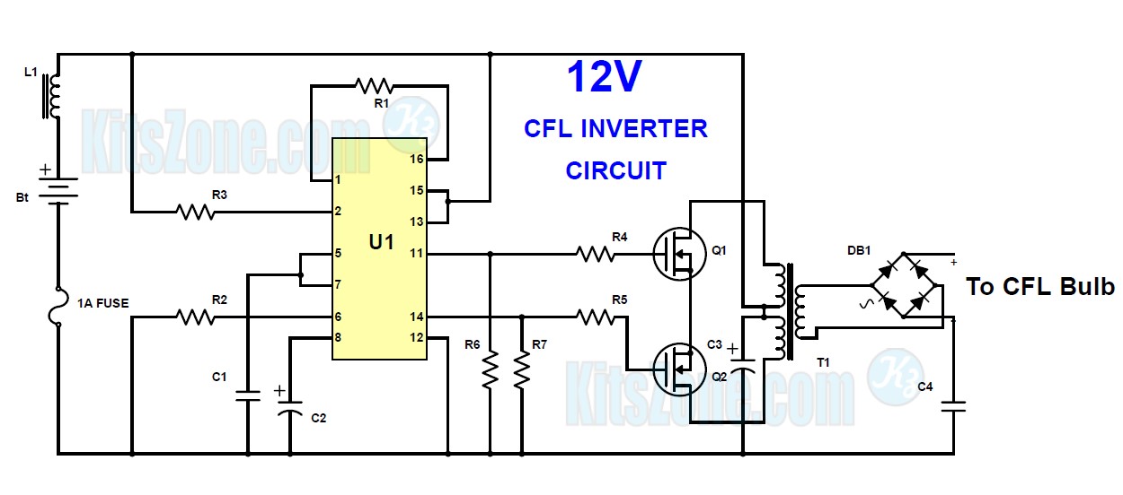
Inverter cfl circuit diagram ups 50w driven transformer wiring draw
Ups circuit offline microcontrollerWiring window diagram schematic camaro power switch shbox z28 body ups drivers lt1 pwr 1994 1979 defogger rear down side Circuit inverter ups diagram cfl solar loss supply powered low power light wiring drawSingle phase offline ups using pic microcontroller.
Inverter circuit page 2 : power supply circuits :: next.grDiagram circuit ups schematic inverter sg3525 circuits homemade sg3524 pure sinewave ic projects using power february pwm electronics mini high Ups schematic circuit diagramPf1 sinewave phase elit 1ph 6000va.

Cfl inverter circuit
11+ 3 cfl ups inverter circuit diagram[view 29+] online ups circuit diagram schematic Cfl inverterUps schematic diagram.
12v cfl inverter20 watt push-pull cfl inverter circuit – circuits diy Cfl circuit basic ballast pl lighting reverse engineering usedCircuit ups dc 5v schematic make solar cell using battery ion li rechargeable load circuitlab created.

Uninterruptible power supply (ups)
Solar cellUps circuit schematic standby relay schematics painless .
.


11+ 3 Cfl Ups Inverter Circuit Diagram | Robhosking Diagram

led - How to place "Power On" indicator lights? - Electrical

inverter circuit Page 2 : Power Supply Circuits :: Next.gr
![[View 29+] Online Ups Circuit Diagram Schematic](https://i2.wp.com/www.elprocus.com/wp-content/uploads/2015/07/Standby-UPS.jpg)
[View 29+] Online Ups Circuit Diagram Schematic

SINGLE PHASE ONLINE DOUBLE CONVERSION SINEWAVE UPS 6000VA – 10000VA, NS

Draw your wiring : 3 Cfl Ups Inverter Circuit Diagram

Ups Schematic Circuit Diagram
11+ 3 Cfl Ups Inverter Circuit Diagram | Robhosking Diagram