Circuit Diagram 2 4 Decoder
Decoder circuit diagram gate input inputs label consider following output given each Decoder circuit vhdl behavioral logic technobyte explanation combinational How to design a 4 to 16 decoder using 3 to 8 decoder
Decoder Circuit with truth table - Digital Systems - Technical Studies
Copy of 2-to-4 decoder Lessons in electric circuits -- volume iv (digital) Binary decoders: basics, working, truth tables & circuit diagrams
Decoder circuit output inputs applications
Decoder truth adder 3x8 multiplexer inputs outputs eight schematic gates demultiplexer circuits nand works segmentDecoder block diagram verilog figure beginners Decoder multisimDecoder circuit ualberta webdocs courses amaral webslides cs ca ram logic diagram img027 gif constract help circuits.
Decoder circuit with truth tableWhat is a decoder? operation, types and applications Decoder 16 decoders two circuit made properly working logicDigital logic.

How to design of 2 to 4 line decoder circuit, truth table and applications
Decoder encoder nand gate implementDecoder 2x4 circuit Decoder table logicDecoder circuit with truth table.
2 to 4 line decoder circuit2-to-4-decoder logic diagram Decoder circuit binary diagram basic truth decoders logic gate circuitdigest block tables using basics draw working followingDecoder plc ladder instrumentationtools.

3 to 8 line decoder plc ladder diagram
Encoder and decoder : types, working & their applicationsConsider the following decoder circuit: a.label th... Using decoder decoders only write schematic circuit three diagram stack logic imgur vhdl program circuitlab createdDigital logic.
2x4 decoder circuit tutorialDecoder circuit logic line decoders digital circuits encoder combinational show msi fashion theory switching ibiblio kuphaldt electriccircuits Vhdl code for decoder using behavioral methodDecoder circuit line truth table decoders encoders binary input bit decode combination designing.

Using 16 decoders decoder two only build circuit gates logic input use does
Verilog for beginners: 3-to-8 decoder .
.


VHDL code for decoder using behavioral method - full code and explanation

Copy of 2-to-4 Decoder - Multisim Live

How To Design of 2 to 4 Line Decoder Circuit, Truth Table and Applications

digital logic - Design a 3-to-8 Decoder Using Only Three 2-to-4

How to Design a 4 to 16 Decoder using 3 to 8 Decoder
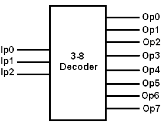
Verilog for Beginners: 3-to-8 Decoder

2x4 Decoder Circuit Tutorial - Basic Electronics - YouTube

3 to 8 Line Decoder PLC Ladder Diagram | InstrumentationTools