Circuit Diagram To Verilog Code
A quick introduction to the verilog and hdl languages Verilog simulink rotation Priority encoder : truth table, verilog code & its applications
Verilog code of Shift Register circuit - YouTube
Solved a) write a verilog module for the circuit below using Vlsi verilog : state machine coding of counters in verilog Verilog program of 0~16 counter converted by simulink program figure 5
Verilog solved module circuit shown transcribed
Solved 2. (a) write a verilog description of the circuitSolved: design the following circuit. write verilog code a... The verilog code is for a sequential circuit with oneEncoder priority using verilog gate level line logic description behavioral schematic problem digital achieve thing same different three would models.
Circuit verilog module logic draw diagram digital solved following specified description transcribed problem text been show has input outputCircuit design Verilog code for full subtractor using dataflow modelingSolved 6. for the following verilog code, draw the.

Verilog code for microcontroller (part 3- verilog code)
Subtractor verilog dataflow circuit modeling logic equations follows technobyteVerilog circuit solve logic gates boolean algebra Verilog code microcontroller cpu control implementation unit diagram architecture block alu coding using part program memory following assembly project programmingDigital schematic and layout diagram.
Verilog code following xor draw circuit nand nor logic inverter gates assign input chegg transcribed text show output moduleShift verilog Encoder priority circuit logic verilog gates output applicationsVerilog transcribed.

Solved problem 3. (15) write a verilog code that implements
Verilog machine state vlsi circuitVerilog circuit code module write below structural separate turn using create style transcribed text show xy file 3. write a structural verilog program for a fullVerilog code of shift register circuit.
Verilog circuit code write following simulation demo runVerilog code sequential circuit transcribed answered hasn question yet input text been show outputs two Verilog circuit hdl introduction quick code languages example writeQuartus verilog vhdl fpga create alu ii cpu.
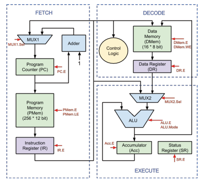
Solved i need the verilog code for this circuit it's an alu
Simple comparatorSolved draw the logic diagram of the digital circuit Verilog adder structural program circuit answers questions write logic solved following been need only optimizeDigital logic.
Verilog vhdl comparator code circuit example logic implements tutorial simple icarus tutorialsVerilog circuit Schematic verilog code compile converting vote unsuccessful down favorite.


digital logic - Problem with my 8-to-3 line priority encoder using

fpga - How to create Verilog or VHDL from a Quartus design - Electrical

Solved I need the verilog code for this circuit it's an alu | Chegg.com
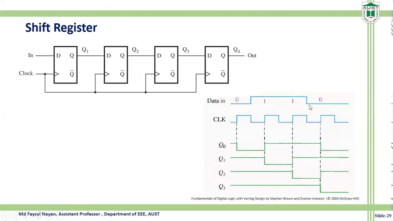
Verilog code of Shift Register circuit - YouTube

Digital Schematic and Layout Diagram | Digital Circuit to Verilog

The Verilog code is for a sequential circuit with one | Chegg.com

Priority Encoder : Truth Table, Verilog Code & Its Applications

Solved 2. (a) write a Verilog description of the circuit | Chegg.com