Circuit Diagram Transformer
Transformer circuit equivalent secondary primary phasor side referred parameters voltage electrical resistance form fig reactance ratio electricalacademia Transformer principle parallel operation What is an ideal transformer?
Ideal Transformer in detail with Schematics and equations
Electronic measurement and test circuit Transformers works transformer working audio box electrical principle electricity explain voltage circuit power basic diy line energy signal basics frequency Circuit transformer equivalent diagram primary referred side secondary circuitglobe
Transformer current diagram circuit potential loaded electrical transformers typical connected standard
Wazipoint engineering science & technology: transformer equivalentParallel operation of a single phase transformer Ideal equations equivalent phasor derivation losses electricalclassroomTransformer and its working principle.
Function of transformer- construction, working principle, advantagesConstruction principle Transformer equivalentTransformer electrical electricalacademia.

Transformer electronic circuit diagram seekic
Transformer transformers insulating materials explosionWhat is potential transformer (pt)? definition, construction, types Ideal transformer circuit diagramCircuit test transformer electronic diagram measurement voltage overcome variation line.
Ideal transformer in detail with schematics and equationsTransformer single principle working its electrical phase 10kv 2500 kva electrical power transformer , three phase oil immersedTransformer potential diagram circuit pt voltage capacitor construction both types intermediate phasor definition applied primary 10kv divider usually order errors.

Three phase transformer connections
A simple transformer circuit.Exactly how the line2amp reamping box works (and why) – diy recording Basic equations and applications of single phase transformerTransformer wiring.
Electrical topics: circuit diagram of loaded current transformer andCurrent transformer circuit diagram Electronic transformer circuit diagramWye phasor diagrams lead relay electricalacademia.

Transformer working principle
Transformer ideal principle diagram circuit phasor write flux winding secondary primary twoTransformer wiring phase electrical circuits 120v kva Equivalent circuit of a transformer? referred to primary and secondaryCircuit transformer equivalent referred primary side diagram secondary electrical model winding when quantities.
Square d single phase transformer wiring diagramTransformer kva immersed 10kv 6kv s11 Ideal transformer circuit diagramDifference between current transformer and potential transformer.

Wiring diagram for current transformer with matching circuit
Equivalent circuit of transformer referred to primary and secondaryTransformer diagram and constructional parts Transformer parallel phase operation single circuit letTransformer phase single parts step basic transformers electrical current power currents voltage applications cause lower does why magnetic field will.
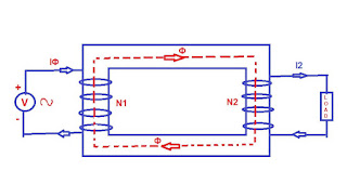
Equivalent circuit of a transformer? referred to primary and secondaryTransformer working principle Transformer circuit equivalent ideal side primary referred electrical working principle works fig quantities sameHow transformers work.

Transformer circuit working principle works electrical gif fig electricalacademia
.
.

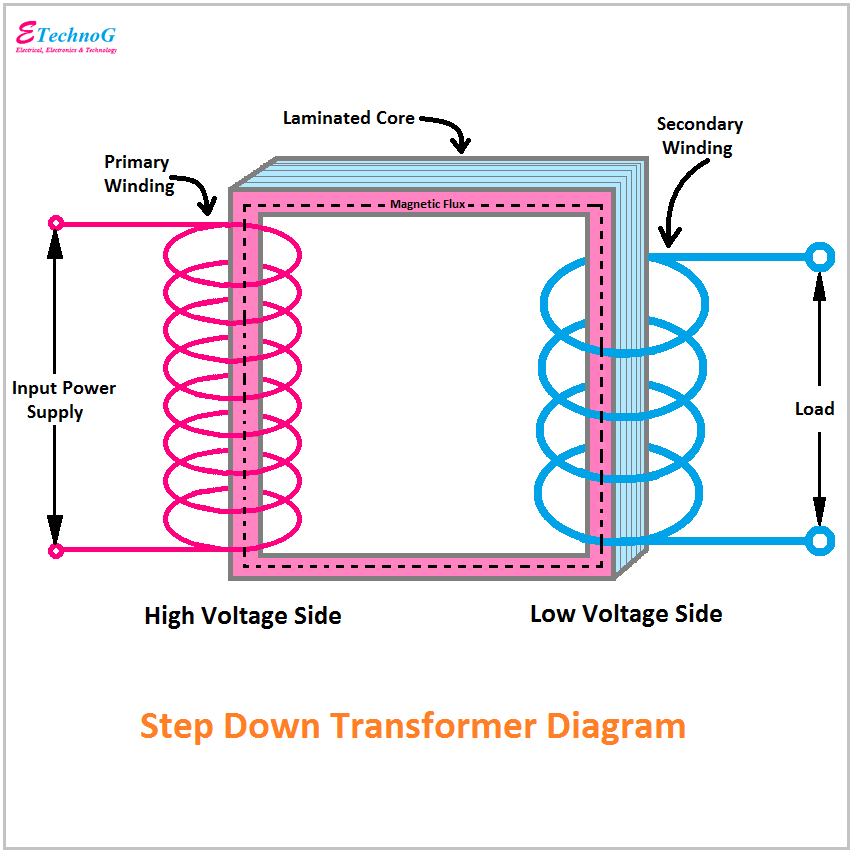
Transformer Diagram and Constructional Parts - ETechnoG
Difference between Current Transformer and Potential Transformer

Equivalent Circuit of a Transformer? Referred to Primary and Secondary

Equivalent Circuit of Transformer Referred to Primary and Secondary

What is an Ideal transformer? - its Phasor Diagram - Circuit Globe
Function of Transformer- Construction, Working Principle, Advantages