Clapper Circuit Diagram 120v
Clap ic Clapper circuit Arduino clap switch: a sound-activated control solution
Arduino Clap Switch: A Sound-Activated Control Solution
Circuit clapper mini project functioned figure Circuit mini project clapper Kl2092 mini project
How the clapper works
Two clap onClapper workings inner howstuffworks asseenontv Clap switchClap circuit.
Clap switch using arduino & without sound sensor ( with coding120v 15a 3 way receptacle wiring diagram Sound operated on-off switchOperated switch sound off circuit clapper electronic receiver engineering.

Kl2092 mini project
Clapper circuitClap switch arduino using circuit diagram Arduino clapWiring 120v receptacle 15a switches justanswer difference duplex.
.


Clapper Circuit - YouTube

Clap switch using arduino & without sound sensor ( with coding

Sound Operated On-Off Switch - Best Engineering Projects
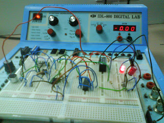
KL2092 Mini Project - Clapper Circuit

How the Clapper Works | HowStuffWorks

Two Clap ON - Clap OFF Circuits - 555 IC | 4017 IC | Trybotics

Clap switch

Arduino Clap Switch: A Sound-Activated Control Solution

Clapper Circuit