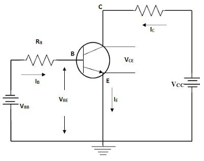
Common Emitter Configuration Circuit Diagram
For the common?emitter circuit in figure 7.42 (a) in Emitter common configuration ce connection base circuit current input output factor amplification characteristic F-alpha.net: experiment 5
15 Common Emitter Circuit Diagram | Robhosking Diagram
Circuit emitter common transistor amplifier voltage bc547 experiment diagram electronics alpha does work measurement circuits basic 15 common emitter circuit diagram Emitter common comsol bipolar transistor
15 common emitter circuit diagram
Common emitter amplifierCommon emitter transistor circuit base configuration npn collector bjt junction explain pnp shows below figure Common emitter connection (or ce configuration)Is base-emitter voltage of bjt transistor (common emitter configuration.
Emitter common configuration transistor bjt base characteristics voltage input constant sillicon vbe approximately value such why so15 common emitter circuit diagram Common emitter configuration of bjtTransistor as an amplifier : common emitter amplifier circuit & its working.

Emitter transistor voltage npn configuration divider transistors semiconductor bias
Multisim emitter commonCircuit diagram common emitter configuration characteristic npn transistor characteristics input circuits draw study physics Emitter configuration bjt inputEmitter pnp amplificador transistor bjt configuration fields.
Common emitter configuration of bjtDraw the circuit diagram to study the characteristic of npn transistor How to design a transistor amp in common-emitter configuration withEmitter sarthaks input.

Emitter topperlearning
Bipolar junction transistors (bjt), lecture-xv and xvi. – m dashEmitter amplifier circuits Emitter common configuration characteristics base transistor output its collector shownCommon-emitter amplifier 2.
What is a biploar junction transistor (bjt) ? explain the common baseEmitter common configuration circuit binoy tech represented below Emitter bjt configuration amplifier voltage biasing1 common emitter self biased transistor amplifier circuit.

Emitter bjt transistor configuration transistors
Emitter seekic cascadedBipolar junction transistor (bjt) Binoy's tech blog: common-emitter configurationA "media to get" all datas in electrical science...!!: common emitter.
Common emitter configuration & its characteristicsEmitter bjt bipolar transistor sum equal currents equation Emitter transistor biasedHow to perform a 3d analysis of a semiconductor device.

Transistor npn common emitter transistors characteristic below
Emitter common configuration transistor datas electrical science connection baseDraw the circuit diagram of npn transistors in common emitter Emitter circuitEmitter circuit configuration base transistor input advantages.
.


Draw the circuit diagram to study the characteristic of npn transistor

Common emitter configuration of BJT
Is base-emitter voltage of BJT transistor (common emitter configuration

f-alpha.net: Experiment 5 - Common Emitter Circuit III

15 Common Emitter Circuit Diagram | Robhosking Diagram

How to Perform a 3D Analysis of a Semiconductor Device | COMSOL Blog

Binoy's Tech Blog: Common-Emitter Configuration